See what I did there?
I should start out by saying it’s been quite a while since I’ve written anything in a “blog” type format, so please be patient if I go off on a long tangent about something that’s powerfully uninteresting to you, my loyal readership.
Since my last post on this blog, I moved to California (San Francisco, specifically), got hit by yet another car while riding my bike, ate many delicious meals in San Francisco, had many successes with work, learned many hard lessons about living in a city, learned many more hard lessons about working with OE manufacturers on engineering projects, and (more relevant to this post) using / understanding / configuring / and making sense of Inertial GPS systems. Let’s go over some basics about the latter.
GPS / GNSS:
Many moons ago, I thought that when you placed a GNSS receiver / antenna on the roof of a race car, you could power it on, science would happen, and then it would tell you where on the earth you were. Magic.
I didn’t spend much time thinking about how it worked, because, well, it worked fine. It provided a nice visualization of where a car was on track. Fine. Great.
Over the past few years it has become increasingly obvious that it’s really important to understand how something works if you’re going to rely on the data it produces. A lot of the projects that I have been involved with over the past few years at some point rely on GNSS. It’s really important to know when to rely on it, when not to rely on it, and why.
sidenote_1: Sander, you keep writing “GNSS”, what does that even mean? “GNSS” stands for Global Navigation Satellite System. Some people often say “GPS” when they actually mean “GNSS”. You could plausibly argue that GNSS and GPS are interchangeable as ways to describe a system that can calculate where you are on the earth, but I felt it was worth mentioning that. GPS is actually a constellation (series of satellites in a specific orbit around the earth) of satellites that are owned and operated by the US Space Force. Yes, that Space Force. There are other constellations that are run by other countries such as “Galileo” (EU), “Beidou” (CN), “Glonass” (RU), “IRNSS” (India), “QZSS” (Japan). A GNSS system may use signals from satellites from one or more of these constellations to calculate your position on the globe. Neat right?
So, this begs the question: How do GNSS systems determine your position? How does it work? SANDER, TELL ME HOW SCIENCE HAPPENS!
sidenote_2: I’m going to do a super high level description of how things work, but if you’re interested in much more detail, you should really checkout this GPS Compendium (by u-Blox AG). It is a treasure trove of information about GNSS systems.
Basic things to know:
- There are a number of satellites (in different constellations, run by different countries) orbiting the earth in a known trajectory / orbit.
- Each satellite has an atomic clock on board to keep accurate time.
- Atomic clocks are cool because they keep very accurate time for a very long time. (Not like your calculator wrist watch that you’re wearing right now. yes, you.)
- Satellites regularly transmit their time so that GNSS receivers on the ground can receive this information.
- If you take in a known position of the satellite, time from the satellite, you can use the speed of light as a constant to determine the distance from the GNSS receiver to the satellite.
- You can determine a 3D position and time error with a minimum of 4 satellites. (Latitude, Longitude, Altitude, delta T error).
- There are many sources of error that can cause accuracy issues (ionosphere time delay, multi-path signal errors, and other things outside the scope of this post)
- The rate in which data is sent from these satellites will limit the rate at which we can calculate our position on the ground
That last bullet point is really the key issue here. Even very very expensive GNSS systems (NovAtel et. others) can not generate high frequency position measurements (lots of position updates every second) with just GNSS data alone. You need more data to help “fill in the gaps” between GNSS position updates. Well, how on earth would we “fill in the gaps”???
IMU (Inertial Measurement Unit):
IMU’s are generally understood to consist of a 3-axis accelerometer and a 3-axis gyroscope. What even is that? Let’s start with the accelerometer.
IMU (Accelerometer):
Like the name implies, the accelerometer measures acceleration. Now, you may be thinking, “Wow, Sander, you’re blowing my mind right now”. Or, maybe you’re not thinking that, hard to say.
I know that’s inherently obvious based on the name, but another way to think about acceleration measurement is that there is always acceleration to be measured (at least on our planet) by way of gravity. If you set a 3-axis accelerometer on a flat table, you will notice that the axis that is pointing up will report approximately 9.81 meters / second / second of “acceleration”. This is the measurement of gravity acting upon the table to keep it from floating away.
What can we do with an accelerometer beyond all of the well meaning, but painfully over simplified, statements about “my car pulled 3g’s off the line” or “I saw 2.5 lat G in T5 at Summit Point”? We can use calculus! From acceleration we can determine velocity doing a single integration, and we can determine relative position doing a double integration!
sidenote_3: I’m intentionally skipping an entire large chunk of explanation about removing gravity from acceleration measurements to actually get something useful from them and before integration to achieve velocity measurements, and entirely skipping bias calculation / error sources, for now.
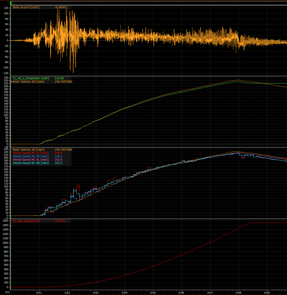
sidenote_4: Live distance traveled channels are being prototyped now and will be added to the sensor firmware later in 2021.
IMU (Gyroscope):
Like the name implies, the gyroscope measures gyroation. (Sorry, this is wildly incorrect, I just thought it would be funny at the time of writing relative to my previous bit about accelerometers measuring acceleration).
Gyroscopes measure the angular velocity about an axis. A simple way to think about this is if you placed a gyroscope on your hipster friends turntable (ya know, for vinyl records), and turned it on, the axis that is pointing straight up will probably indicate ~200 deg/second (33.3 RPM for 12″ records). This is simply measuring the speed at which the turntable is spinning.
What can we do with a gyroscope beyond making your friend with the turntable nervous by telling him it’s actually spinning at 198 deg/second as opposed to the 199.7999999999999999 deg/second it should be? You guessed it, more calculus! From angular rate we can determine the relative angles (more simply put, relative roll, pitch, and yaw) doing a single integration!
sidenote_5: It’s important to remember that in a rigid body (something that doesn’t flex or distort about the axis in which you’re measuring), the angular velocity (and resulting angle after integration) will be the same no matter where you place the gyroscope on the rigid body. Another way to think about this is simply that if you have a motorcycle that does a wheelie, no matter where you mount a gyroscope, the resulting pitch angle after integrating the pitch rate will be the same.
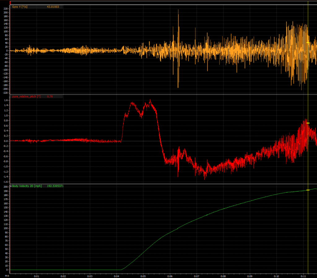
sidenote_6: The pure_relative_pitch [deg] channel has a simple subtraction function to compensate for the mounting of the sensor in the vehicle. The live pitch measurement from the sensor will be absolute pitch (relative to gravity vector).
IMU (Error):
IMU’s are great because they can be light and small and provide very high rate data (1khz +), but it is also important to remember that they can be subject to long term integration error. These errors are omnipresent in in all IMU’s but especially ones that us common folk (read: not military) are allowed to buy.
Cheap IMU’s (less than a $10,000.00 or so) are usually Micro Electrical Mechanical System (MEMS) based units. They’re great because they’re small, cheap, light weight, and low power. But they are prone to massive error (usually mainly based around temperature, but there are other sources of error, too) if doing numerical integration over long time windows.
sidenote_7: “…long time windows” are definitely relative. Many consumer grade sensors (cheap) can even start showing integration error in seconds! On the flip side, many tactical grade (usually military only and > $10,000) will measure their integration error in hours)
These errors are tough to calibrate out, and are better addressed if you have another reference to compare your velocity and position to, periodically.
INS (Inertial Navigation System):
Here are some things we now understand:
- GNSS systems can be highly accurate, but the rate at which they can provide position updates is relatively slow.
- IMU’s can provide very fast measurements from which you can determine position, velocity, and orientation. However, their accuracy can become quite poor very quickly when doing single (or double) integrations.
An Inertial Navigation System (INS), combines these two sensors and uses the global accuracy of a GNSS system and the speed of an IMU! These INS systems use some derivative of a Kalman Filter (non-linear Extended or Unscented) to combine these sensor inputs perform what is sometimes called “Sensor Fusion” to generate one smooth cohesive output.
sidenote_8: Kalman Filters are a constant source of interest and wonder, however I think explaining how they work is outside of the scope of this blog post.
What is the point of this wall of text:
Well, I have put together an Inertial GPS system that I would like to sell. I am simply calling an INS. It uses a tried and true Extended Kalman Filter that is very robust and platform (or motion model) agnostic (car, motorcycle, plane, rally-car (read: plane)). I have tried really hard to make integrating this sensor as easy as is humanly possible to any modern, high-end data analysis / control system.
Here are the features:
- 400Hz 32-bit Position (Latitude, Longitude, Altitude)
- 400Hz 32-bit Velocity (Body X, Body Y, Body Z, and 2D Speed)
- 400Hz 32-bit Body Frame Acceleration (Gravity Removed) (X, Y, Z) with online acceleration bias compensation
- 400Hz 32-bit Angular Rate (X, Y, Z) with online gyro bias compensation
- 400Hz 16-bit Orientation (Roll, Pitch, Yaw (Degrees))
- 100Hz “MoTeC GPS” simulation option for integration with MoTeC M1 ECU applications with locked firmware (GT-R, Lamborghini, etc…)
- CAN (1mbps) Output
- Extensive integration support (MoTeC Dash Config, MoTeC M1 Build Project Module, DBC file)
- CNC aluminum enclosure with Deutsch ASL connection and optional IP68 sealing
- Custom firmware available for customer specific addressing, precision, transmit rates, conversions, units, additional on-board math channels, etc…
On the www.obsidianeng.com/downloads page you will find manuals, DBC files, MoTeC dash configuration files, and MoTeC M1 Build Modules.
The sensors will be available for purchase in Q1 2021. The cost will be $4500.00. Please shoot me an email (sander at_sign obsidianeng.com) with more questions.