It’s been a year since we last spoke. I thought that there couldn’t be a better topic to discuss than coordinate frames and rigid body transforms. </sarcasm>. In all seriousness, it’s a great concept to grasp solidly and hopefully will help you do the things that you do with inertial sensors more betterer.
Coordinate frames give you a reference of how you are moving through space. For a quick refresher, we understand that acceleration can be integrated to produce velocity, and velocity can be integrated to produce a relative position. This is all well and good, but if you do not have a proper understanding of which axis is forward, which axis is left, or which axis is up, integration of any of these data products will be wholly irrelevant.
Coordinate frames (based on our current understanding of the physical universe) are represented by three axis’, an X Y and Z. All of these axis are orthogonal to one another (simply meaning that they meet each other at 90 opposing degree angles). It can be somewhat difficult to understand which axis is which without a physical reference (a 3D object that can represent a coordinate frame that you can manipulate) or identification (a 2D image of a coordinate frame) to look at.
UNTIL NOW
…well, hopefully
Sidenote_00: I touched on this hand gesture in the last blog post, but it’s useful to go over again.
A useful thing to understand about coordinate frames is that most (used in evaluation of vehicle dynamics) follow a “right hand rule” convention. If you follow these steps below, you too can be like many physics / robotics researchers and make strange hand gestures when trying to intuitively comprehend coordinate frame rotations (which we will get to later).
– Make a fist with your right hand
– Stick your thumb out while still keeping the rest of your fingers in a fist
– Rotate your hand so that your thumb is pointing toward the sky
– Stick your pointer finger out so that it is pointing away from your body
– Stick your middle finger to your left
You have just created a coordinate frame. Following the right hand rule convention, your pointer finger is pointing forward and represents the +X axis, your middle finger is pointing toward the left and represents the +Y axis, and your thumb is pointing up and represents the +Z axis. You can represent any rotation of a right hand rule coordinate frame!
So now you’re probably thinking, “wow sander amazing”. I know. Just wait.
FLU, FRD, WAT?
The Bosch Motorsport MM5.10 IMU is relatively ubiquitous and used in many race cars. A non-motorsport version is even shipped as standard equipment in some of the most popular electric cars that are on the public roads today. The MM5.10 sensor coordinate frame is represented by the same funny hand gesture that I just made you do. This is referred to in short hand as a FLU (Forward, Left, Up) frame. Meaning that X+ is Forward, Y+ is Left, and Z+ is Up.
Sidenote_01: This FLU frame is described by the ISO 8855 standard. Mainly used in ground traveling vehicles.
The Obsidian INS and IMU products use a different coordinate frame from the MM5.10 IMU. We use a FRD (Forward, Right, Down) frame. Meaning that X+ is Forward, Y+ is Right and Z+ is Down.
Sidenote_02: This FRD frame is described by the ISO 1151 standard. Mainly used in aircraft.
You’re still holding your hand in the hand gesture that I asked you to just a little bit ago, right? If that’s the case, you can easily rotate your hand around the X axis (your pointer finger, in this case) 180 degrees, and voila, you went from holding your hand originally in an FLU frame and now you’re holding your hand in an FRD frame. Using this hand motion, it’s relatively easy to come up with the intuition that, if we want to compare data between an MM5.10 and an INS we will either need to mount the MM5.10 upside down, or mathematically rotate it after the fact.
SIdenote_03: WAT
Aligning frames unrealistically
In practice, it’s normal to see a vehicle outfitted with one or more inertial measurement sensors and sometimes they can be from different manufacturers that have different coordinate frame standards. Using the examples above, lets assume for a moment that we have a vehicle with an MM5.10 using a FLU convention and an INS using a FRD convention. In this case we will assume that the MM5.10 is mounted directly on top of the INS (to reduce the math to pure rotation only).
Sidenote_04: Three color coordinate frames are usually represented by X == red, Y == green, Z == blue
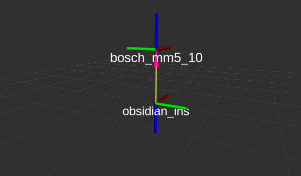
The dumb (and / or) simple way to align these two reference frames is to take the data products (accel and angular velocity) of the MM5.10 in the Y and Z axis and multiply them by -1. This will very simply invert the data produced from the MM5.10 on those axis’ and you will have successfully “rotated” the FLU frame so that is now an FRD frame. For example, you can take the Y axis acceleration of the MM5.10 and multiply by -1 and that acceleration will line up with the raw Y axis acceleration of the INS.
The visualized frame would mathematically look like this below:
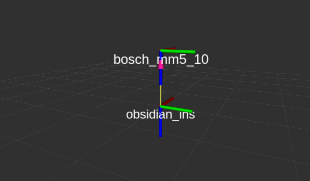
After rotation the MM5.10 in to the same coordinate frame as the INS, the angular velocities (yaw rate, pitch rate, roll rate) would theoretically be the same, and the acceleration measurements would be almost the same (we’re not accounting for translations here to keep this post a little shorter). Easy peasy.
Which way is positive?
One of the most common questions I get about the INS / IMU has to do with direction of rotation. e.g. “Which direction is +10 degrees of pitch? Is the car pointing toward the sky or towards the ground?”. Thankfully, this is a fairly easy thing to intuitively solve when you use your very useful hand gesture that I described above.
Using your hand gesture, make a FLU coordinate frame to represent the MM5.10. This should make it such that your thumb is pointing toward the sky, your pointer finger is pointing forward, and your middle finger is pointing toward the left.
Maintaining that gesture, look at the tip of your thumb. If you rotate your hand around your thumb in a counterclockwise direction, this will be a positive rotation. The images below show a coordinate frame with a yaw value of 0, and a yaw value of +20 degrees.
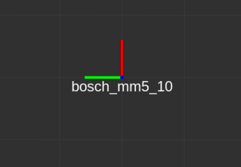
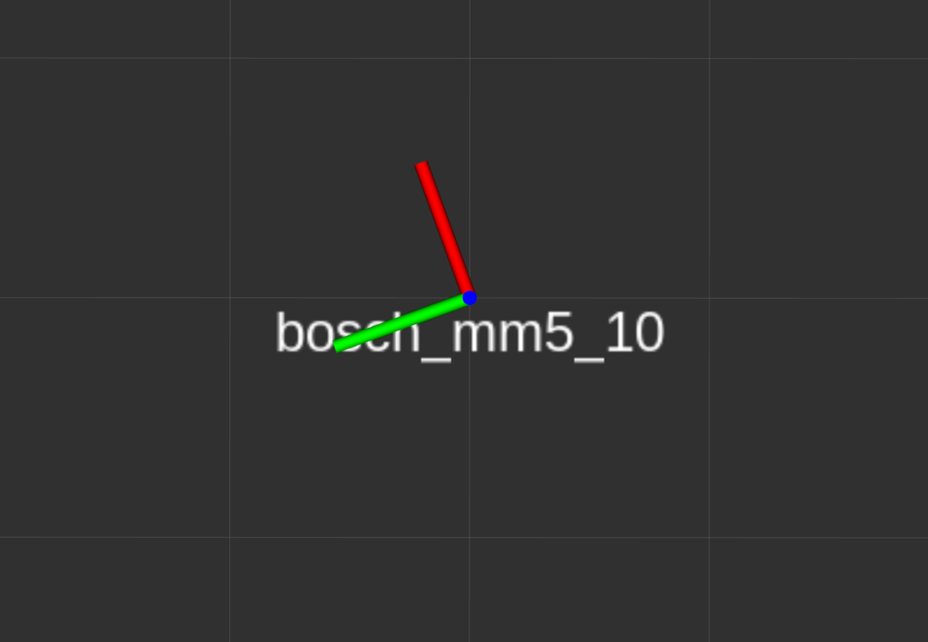
A top down view of the MM5.10, looking in to the Z axis, where the X and Y axis are rotated with respect to the grid below. This would represent a yaw value of +20 degrees.
The same thing would apply for pitch and roll, as well. “Look” in to the positive axis (In an FLU / FRD frame, X for roll, and Y for pitch), and what ever direction is counterclockwise will be a positive rotation.
Aligning frames realistically
While I’d like to tell you that you can align coordinate frames by multiplying with -1, that’s not realistic. We exist in a very non binary world. Which is great for everyone. Imagine how hard it must be for computers that only know 1 and 0.
It’s not unrealistic to say that many race cars have less than perfect mounting of inertial sensors. In this example, let’s imagine a team trying to use an accelerometer in a dash logging display (MoTeC C1XX), or ECU (MoTeC M1XX) for driver analysis. It’s somewhat unlikely that the dash or ECU will be mounted so that the axes of the accelerometer are pointed exactly in the direction of motion that you are interested in (the vehicle’s natural coordinate frame). Maybe the dash / ECU is mounted “mostly straight” in the direction of travel, and / or “mostly perpendicular to gravity”. That doesn’t help us much if we’re trying to use this acceleration data for driver analysis.
Imagine that we are trying to use a MoTeC C127 dash that is angled at the driver like this:
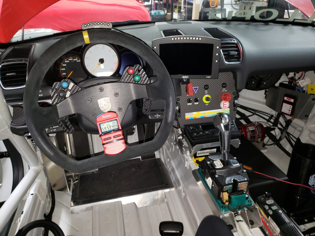
The MoTeC dash pictured above is angled such that the screen is visible to the driver. Being that the accelerometer in the MoTeC dash display is mounted to the PCB internal to the display itself, it’s reasonable to assume that the display being mounted at an angle will result in the accelerometer being mounted at an angle as well. In the interest of simplicity (as this post is already really long and we haven’t even done any math yet) we will assume that the MoTeC dash has zero roll, and zero pitch, with respect to the vehicle coordinate frame. The only thing we would notice in this case is that if the car is traveling exactly straight you may have acceleration in X and Y axes (assuming an FLU frame for the MoTeC dash itself and FLU for the vehicle frame).
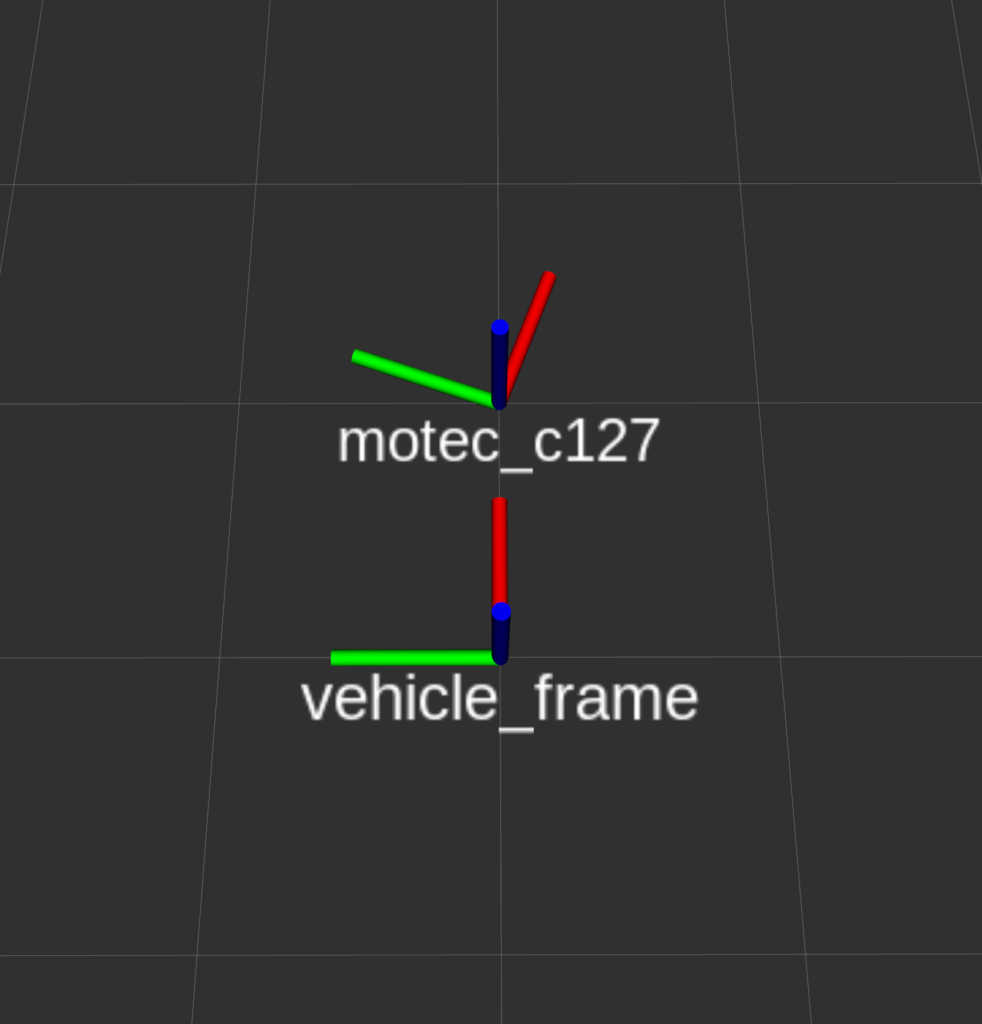
It’s relatively intuitive to see that if the vehicle is traveling exactly straight about the X axis (red in vehicle_frame), you will see acceleration in the X and Y axis in the MoTeC dash due to it’s mounting. Let’s work out how to mathematically rotate the accelerometer so that the data from the MoTeC dash is producing data as if it were mounted exactly straight (inline with the vehicle_frame).
I’ve made some simulated accelerometer data from a MoTeC dash if the vehicle was traveling straight at 9.81 m/s/s constant for 1 second (sampled at 10khz), mounted at some unknown yaw angle with respect to the vehicle_frame above.
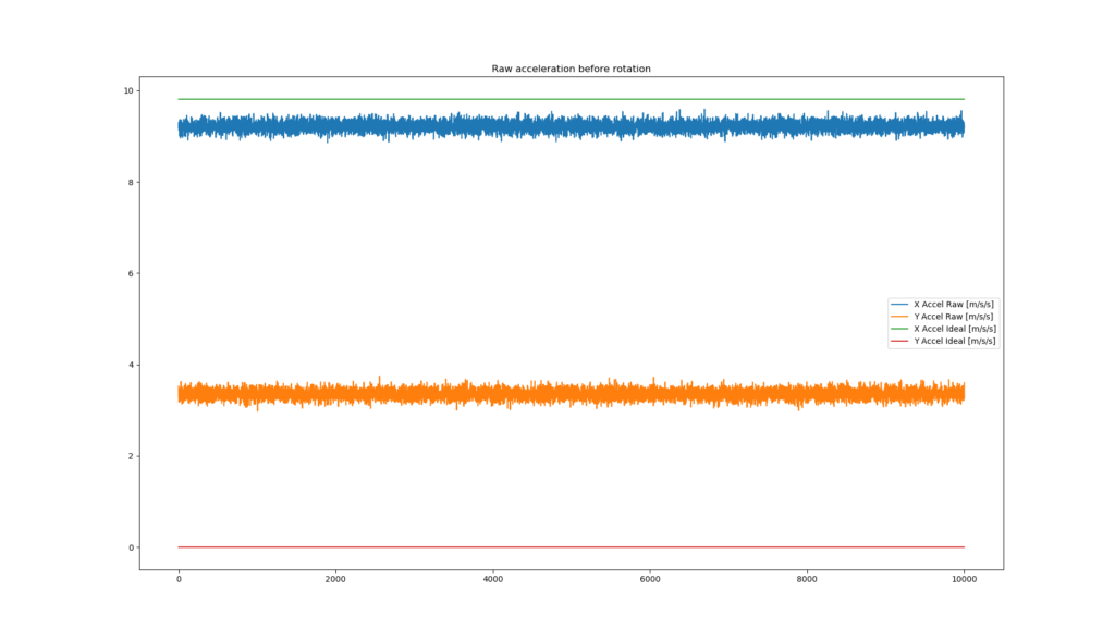
We can use the following steps to rotate this data such that it aligns so that Y and Z are equal to roughly 0.0, while X is equal to 9.81 m/s/s.
codenote_00: python-pseudo-code
# step 1
# find the mean of each axis of acceleration
ax_mean = mean(raw_accel_x)
ay_mean = mean(raw_accel_y)

# step 2
# "guess" a suitable yaw angle of the motec_c127 with respect to the  vehicle_frame
guess_yaw_degree = -15.0

# step 3
# convert guess_yaw_degree to radians
guess_yaw_radians = guess_yaw_degree * pi / 180.0

# step 4
# find the resulting acceleration after rotation using 1D rotation formula
corrected_accel_x = ax_mean * cos(guess_yaw_radians) - ay_mean * sin(guess_yaw_radians)
corrected_accel_y = ax_mean * sin(guess_yaw_radians) + ay_mean * cos(guess_yaw_radians)

# step 5
# repeat steps 2 -> 5 until your corrected_accel_x is equal to roughly 9.81 and corrected_accel_y is equal to roughly 0.0
After you find your guess_yaw_radians channel, you can apply step 4 to all of your raw data and you should have a plot of data that looks like this!
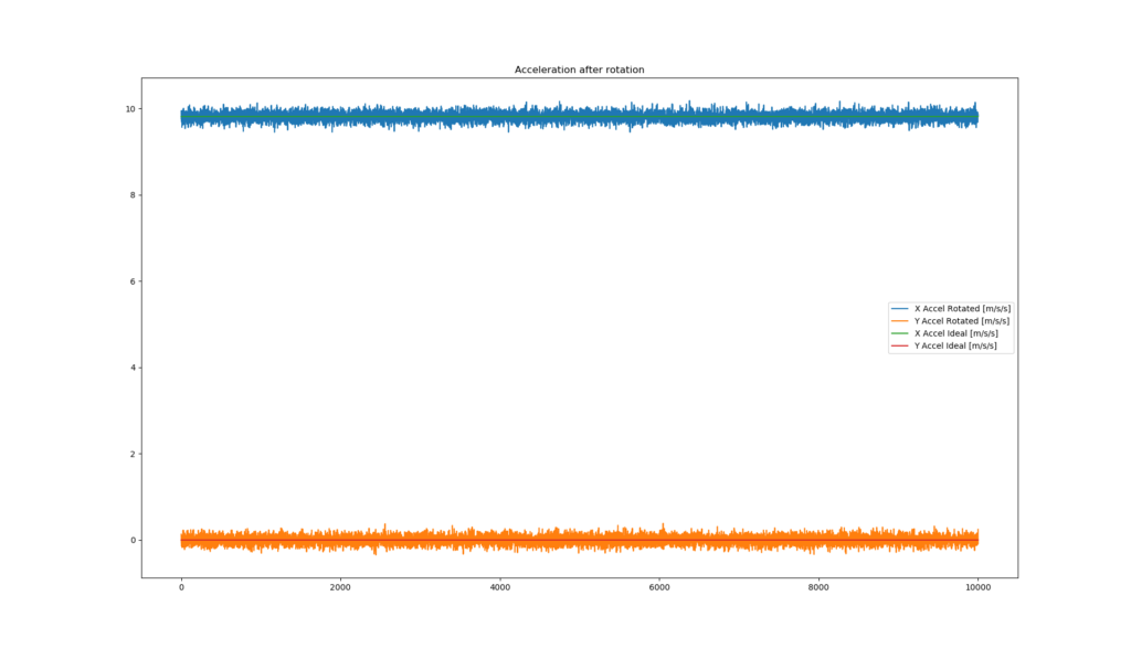
So, you’ve done it. After that work you should have successfully applied a 1D rotation to acceleration data and after this equation, the data from your MoTeC dash should have been mathematically corrected such that the data would be the same if the MoTeC dash were mounted in the same orientation as the vehicle_frame.
BUT WAIT. THERE’S MORE.
Imagine that the MoTeC dash needs to be rotated in more than one axis (yaw only in the example above), what about a yaw rotation and a pitch rotation? Or worse, what about a yaw rotation, a pitch rotation, AND a roll rotation? What are we to do?
The answer is much more complicated and much more difficult to hand estimate using a “brute force” approach that I’ve described above. It is made simpler by applying the rotation in one operation using a rotation matrix as opposed to euler angles* (roll, pitch, yaw), which can be very annoying to deal with when doing 3D rotations.
Sidenote_05: Euler angles are actually often misrepresented as Tait-Bryan angles.
Fin
I do realize that I glossed over details of translation components in proper rigid body transforms. Honestly, I didn’t realize that it would be this difficult to convey this concept in a pseudo-math pseudo-code way that was easily digestible while still keeping with my normal style of posts. Thanks for sticking with it. If you made it this far, you’ve earned some relaxation

