Simulator

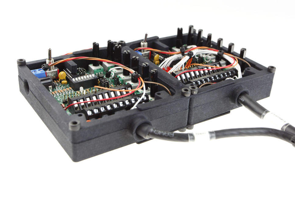
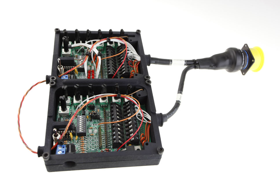
The simulator kits that I have been putting together are based around an already existing board that consists of three 0-5 volt outputs, two thermistor outputs (temps), and one digital or analog speed output. I have designed and manufactured plastic, 3D printed, enclosures that are expandable to enclose 1, 2, or 3 of these boards. Along with the enclosures, the boards will be pre-wired to a Corsair 18-32P connector, or a Corsair 22-55P connector, depending on the kit purchased.
From these pre-wired connections, you will be able to purchase adapters to connect the simulators to the ECU that you wish to use. If for instance you initially purchase a simulator kit for an AEM Infinity 6/8h ECU, and you decide to switch to a MoTeC M130 ECU, you can simply buy an adapter that will allow you to still use the simulator kit you originally purchased.
The kits will be setup as follows:
The Basic 4 or 6 cylinder kit will provide you with:
-Three 0-5 volt potentiometer (user adjustable with a knob) outputs.
-Two thermistor based potentiometer (user adjustable with a knob) outputs.
-One analog (mag), or digital (hall effect) engine speed output (user adjustable with a fine and coarse knob). (Default set to 60-2 Ref, +1 Sync).
-There will be two LED’s on the board to signify when the first and second bank of injectors are firing.
-There will be six LED’s on the board to signify when the ignition coils are firing.
-There will be LED’s for two auxiliary outputs.
-There will be an LED for fuel pump activation.
-There are also male pins on the board, and screw terminals so that you may jump, test, and verify the outputs that the ECU is driving with an oscilloscope, test light, or any other measurement device.
-The simulator will be wired to a Corsair MS18-32
The Intermediate 4 or 6 cylinder kit will provide you with:
Everything that the single kit has, times two.
-Six 0-5 volt potentiometer (user adjustable with a knob) outputs.
-Four thermistor based potentiometer (user adjustable with a knob) outputs.
-One analog (mag), or digital (hall effect) engine speed output (user adjustable with a fine and coarse knob). (Default set to 60-2 Ref, +1 Sync).
-One digital (hall effect) speed sensor. This can be used for simulating driven wheel speed, turbocharger speed, output shaft speed, or any number of other speed / frequency based inputs.
-There will be four LED’s on both boards to signify when the first and second bank of injectors are firing.
-There will be six LED’s on the board to signify when the ignition coils are firing.
-There will be four LED’s on both boards for auxiliary outputs.
-There will be an LED for fuel pump activation.
-There are also male pins on the board, and screw terminals so that you may jump, test, and verify the outputs that the ECU is driving with an oscilloscope, test light, or any other measurement device.
-The simulator will be wired to a Corsair MS18-32
One of the significant advantages of the 4 or 6 cylinder basic and intermediate kit is that they’re both going to be wired to the Corsair MS18-32 connector with the same pinout. This means that if you buy a basic simulator at one time, you can have your sim sent in to be upgraded to the intermediate simulator while still being able to use your original ECU adapter harness.
The Intermediate 8 cylinder kit will provide you with:
Everything that the single kit has, times two.
-Six 0-5 volt potentiometer (user adjustable with a knob) outputs.
-Four thermistor based potentiometer (user adjustable with a knob) outputs.
-One analog (mag), or digital (hall effect) engine speed output (user adjustable with a fine and coarse knob). (Default set to 60-2 Ref, +1 Sync).
-One digital (hall effect) speed sensor. This can be used for simulating driven wheel speed, turbocharger speed, output shaft speed, or any number of other speed / frequency based inputs.
-There will be four LED’s on both boards to signify when the first and second bank of injectors are firing.
-There will be eight LED’s spread across both boards to signify when the ignition coils are firing.
-There will be four LED’s on both boards for auxiliary outputs.
-There will be an LED for fuel pump activation.
-There are also male pins on the board, and screw terminals so that you may jump, test, and verify the outputs that the ECU is driving with an oscilloscope, test light, or any other measurement device.
-The simulator will be wired to a Corsair MS22-55
The Advanced Universal kit will provide you with:
Everything that the single kit has, times three.
-Nine 0-5 volt potentiometer (user adjustable with a knob) outputs.
-Six thermistor based potentiometer (user adjustable with a knob) outputs.
-One analog (mag), or digital (hall effect) engine speed output (user adjustable with a fine and coarse knob). (Default set to 60-2 Ref, +1 Sync).
-Two digital (hall effect) speed sensor. These can be used for simulating driven wheel speed, turbocharger speed, output shaft speed, or any number of other speed / frequency based inputs.
-There will be four LED’s on both boards to signify when the first and second bank of injectors are firing.
-There will be twelve LED’s on two out of the three boards to signify when the ignition coils are firing.
-There will be six LED’s on both boards for auxiliary outputs.
-There will be an LED for fuel pump activation.
-There are also male pins on the board, and screw terminals so that you may jump, test, and verify the outputs that the ECU is driving with an oscilloscope, test light, or any other measurement device.
-The simulator will be wired to a Corsair MS22-55
All that is required to power these is a 12VDC AC Adapter. If you have a bench top power supply, I can provide you with test leads to plug in to the power supply.